Augmented Reality
Augmented Reality: Enabling Component for Effective Live Virtual Constructive Integration
Authors:
Frank Dean — Principal Investigator
Simulation & Training Technology Center, US Army RDECOM
12423 Research Parkway
Orlando, FL 32826-3276
Frank.Dean@us.army.mil
Sheila Jaszlics — President
Richard Stilson — Engineer
Scot Sanders — Engineer
Pathfinder Systems, Inc.
5525 West 56th Ave, Suite 400
Arvada, CO 80002-2804
sheila@snakephotographer.com
rstilson@snakephotographer.com
ssanders@snakephotographer.com
Abstract
This paper describes the results of a RDECOM research project called the Dismounted Augmented Reality Training System (DARTS). The DARTS prototype that was developed under this effort provides encouraging data and a confidence that the tools and techniques that are necessary to implement this technology, in a live military training environment, are not far off. Ultimately the key to successful implementation and use of this emerging technology is for trainers to understand its potential uses and to place command emphasis on further development for specific military uses.
Introduction
Imagine the Warfighter having an effective embedded capability to train anywhere, anytime without the need for prolonged preparation. Given the amount of time and fiscal resources invested into various types of military training systems, one of the most efficient ways to reach such a goal would be to merge existing and planned systems, into a larger integrated environment. In other words, blur the lines or boundaries, both physically and mentally, that separate the Warfighter’s training into the discrete live, virtual and constructive training environments that we use today.
With such a capability, trainers can mix-match or plug-play the appropriate and available systems to meet the appropriate training objectives. Along these lines, one of the Army training community’s major areas of interest is implementing live, virtual and constructive integration. Unfortunately, from the current LVC-IA prospective, there is no two-way flow and presentation of training data between the live training domain and the virtual-constructive training domains. Ongoing LVC research and acquisition efforts focus mainly on the transmission of the live participants’ position data into the virtual domain for viewing and interaction. However, live participants cannot “see” the real-time rendering of personnel, vehicles, fire and effects, etc. that originate from the virtual domain. In order to effectively “Train the Force, How and As It Fights!” there must be a complete replication of complex operating environments. For a truer picture of complex operating environments, there must be full integration—a two way street for data flow across the training domains. If data and information flow is only in one direction, then the architecture is not and cannot be declared “fully integrated.”
Being the new paradigm of transformation in training, what would an LVC integrated complex training environment look like? Image the following scenario:
Members of a small unit are engaged in a live training exercise in Ft. Lewis, WA or Ft. Hood, TX. During the exercise there is a call for close air support, which is provided by a pilot who is training in an aviation combined arms trainer, located in Ft. Rucker, AL or Ft. Bragg, NC. On the approach to provide close air support, the pilot’s monitors provide an integrated view of the battle space, including icons/avatars representing the tracked positions of the small unit members. While operating in the virtual environment, the pilot can see the small unit members; however, the small unit operating in the live environment is not able to see and react to the pilot’s actions, without some intervention from perhaps an observer-controller (O-C). A truly integrated complex environment would permit the small unit that is operating on the ground to at least observe the aircraft and any fire and effects resulting from the pilot’s mission. Currently that does not happen. What technologies can be developed and brought to bear, in order to provide a more effectively integrated training environment and capability for this and similar scenarios? Is there a solution that could be available that would permit a mounted or dismounted Warfighter, who is operating in the live environment to “see” and “interact” with those who are operating virtually or constructively? The answer is “yes!” The solution is Augmented Reality.
Live Virtual Constructive-Integrated Architecture (LVC-IA)
(Information taken from Project Manager for Future Force (Simulation))
LVC-IA Concept
The LVC-IA integrates current and future Live, Virtual, and Constructive simulation systems in order to stimulate battle command systems for mission planning, rehearsal, and training. Thus, LVC-IA provides an integrated LVC training environment that expands the available battle space, while allowing the training environment to more closely approximate the operational environment. An integrated LVC environment enables on-demand, distributed mission planning, rehearsals, and training that is required to gain and maintain skill proficiency in battle space awareness, force application, focused logistics, and protection.
LVC-IA Plan
-
Implement a standardized set of protocols, specifications, and standards that permit interoperability and integration among Army & Joint LVC components.
-
Provide an integrated LVC environment that ensures compatibility and interoperability for all TADSS and fully embeds into Future Force Battle Command System, while linking to and stimulating Joint Command and Control (JC2) systems.
-
Provide Plug-and-Train capability to support operations, mission planning-rehearsal, on demand, anytime, and anywhere, while training in a Joint context.
-
Permits interoperability and integration among- a. Joint Family of Simulations (JFOM) & (JNTC Efforts). b. Common Training Instrumentation Architecture (CTIA). c. Synthetic Environment (SE) Core. d. Army Constructive Training Federation (ACTF). e. Test and Training Enabling Architecture (TENA). f. Other Potential LVC components (FCS FoS, WIN-T?). g. Embeds into and stimulates JC2.
Augmented Reality
What is Augmented Reality (AR)? AR techniques enhance the Warfighter’s live view of the complex training environment, by providing text, graphics, 2D/3D objects and other information in real time. Thus, AR provides the Warfighter, operating in the live environment, with a greater awareness of impacts from overlapping virtual and constructive training simulations. This computationally intensive means of merging live and virtual entities into one seamlessly integrated view of battle space can provide commanders and trainers with the ability to mix live-virtual-constructive training missions, as well as coordinate and integrate various training effects across different environments. Used appropriately, AR can increase the realism and effectiveness of live training, from both mounted and dismounted prospectives, while merging with the virtual and constructive training domains.
Although at the present time the U.S. Army does not have a definitive requirement for the use of Augmented Reality, recent research conducted at the Simulation & Training Technology Center (STTC), Research, Development & Engineering Command (RDECOM), Orlando, Florida suggests that Augmented Reality may be used in a broad variety of army training applications. The concept of Augmented Live Environments has the potential to create interactive, multi-sensory, non-linear environments that provide the Warfighter with unparalleled and realistic live training and experiential learning. Such a capability would potentially provide commanders and trainers with creative and flexible solutions sets for the ever-changing and fluctuating missions and training requirements of the modern Warfighter.
What are the technology challenges to providing Augmented Reality capabilities to the Warfighter? This question is best answered by examining some recent research. The Dismounted Augmented Reality Training System (DARTS) is an U.S. Army RDECOM funded project which sought to research AR technology issues. DARTS was originally initiated under the Embedded Technology Dismounted Soldiers, Science & Technology Objective (ETDS STO), which ended in Fall 2004. Additional DARTS work was funded and continued under the Embedded Combined Arms Team Training, Army Technology Objective (ECATT ATO) and culminated with a technology demonstration in December 2005.
In spite of limited funding, Pathfinder Systems, Inc has taken a difficult problem—implementing real-time, tether-less, man-wearable Augmented Reality—and has designed a developmental prototype, which was demonstrated in December 2005. Although funding constraints have delayed additional work in this area, a number of issues and valuable information were identified for future analysis and research. The remainder of this paper describes the results of this research.
Dismounted Augmented Reality Training System (DARTS)
The goal of the DARTS effort was to demonstrate that it is possible to develop a working Augmented Reality (AR) system that can operate in real-time, using a compact, non-intrusive, equipment suite worn by a war fighter. Our goal was to make our AR system operate in an environment that was not pre-surveyed, instrumented, or otherwise prepared in advance in order to operate. Previous AR systems have been unable to operate in real-time, or they required the use of an extensive non-mobile infrastructure. Many AR systems require the use of a complex grid of pre-measured marker points to operate. Clearly, AR that requires such significant pre-processing of the environment is not the most desirable technology solution for the fast-paced, live or embedded military training applications.
The goal of the DARTS AR system was to insert virtual objects (in this case a virtual Infantry Combat Vehicle or ICV) into the field of view of a user by means of a see-through head mounted display (HMD). The virtual object must be placed in the user’s field of view so that it appears as if it were a real object with a physical location in the real world. Since the virtual object is actually just a projection in the HMD, the displayed position of the virtual object needs to move as the user moves his head, so that the virtual object will appear to be fixed in a real location. The user should be able to walk towards the ICV and see it get larger as he gets closer. Likewise, the user should be able to walk around the ICV and view its front, back or sides from different angles. Finally, if a real object, like a bush or another person, comes between the AR user and the tank, the portion of the ICV that would be blocked from view should not be displayed. All of these goals have been achieved to some degree by previous AR research efforts, but they have not been done in real-time, using a man-worn system, operating in an unprepared environment.
In our effort we also needed to demonstrate the ability to insert useful AR content into a user’s field of view, in a way that can contribute to military training and operations. This might include displaying situational awareness data in the form of object outlines, or marker icons. It can also allow an AR system user to participate in a simulation, so that units from a simulation training exercise are displayed as virtual objects that the user can interact with. We established a set of requirements for the base effort with these general goals in mind. The specific goals of this base effort were to:
-
Inject virtual entities into a real world real-time scene
-
Accommodate real world objects that block the view of a virtual object
-
Integrate a simulated Infantry Combat Vehicle (ICV) into the user’s view
-
Demonstrate a two-way Distributed Interactive Simulation (DIS) protocol interface with US Army RDECOM’s Infantry Combat Vehicle Testbed
-
Demonstrate the ability to operate a man-worn, non-tethered AR system
These goals are graphically presented below:

Inject virtual entities into real world, real-time scenes

Accomodate real-world objects
Infantry Combat Vehicle (ICV) Testbed

Non-tethered, man-worn AR capability
DARTS Program Accomplishments
Our DARTS demonstration, conducted in December of 2005, was successful. We were able to demonstrate a man-worn AR system that allowed a DARTS user to interact with a virtual ICV that was presented in the DARTS HMD. The user was able to view the virtual ICV in the real-world, real-time environment from different viewpoints. The DARTS user was also able to watch the virtual ICV move in the real-world, real-time environment. A summary of the components that helped us realize this accomplishment are summarized here:
Two-way DIS Interface: We developed software to receive and decode DIS Protocol Data Units (PDUs) from a network connection, and also to encode and send DIS PDUs. We developed code to convert entity position and orientation between the world coordinate frame used by the ICV testbed to a local coordinate frame used by DARTS.
Virtual Entity Control: We integrated our DIS PDU communication software into DARTS so that we could use the position and orientation coordinates from an incoming PDU to determine the position of a virtual object with respect to the DARTS entity. We also developed code to convert the local position of the DARTS entity into world coordinates, and send those coordinates in an outgoing DIS PDU. We developed and demonstrated an initial DIS interface with the ICV simulator which allowed virtual and live entities to interact with one another and allowed a dismounted user to see a virtual entity in a real-world, real-time view.
Wireless Position Tracking: We developed software to access the Ubisense wireless position tracking system and obtain position updates several times per second. This position data is used to allow the DARTS system to determine where it is relative to the world, so we can determine how a virtual entity should be displayed in the DARTS system as well as how the DARTS user should be displayed in the virtual world of the ICV Testbed displays. This capability was used to allow for early demonstrations, as we develop our objective point tracking and pose recovery algorithms that will not require the use of any additional infrastructure beyond the equipment that is worn by the soldier. These new pose recovery algorithms will eventually replace the positioning data provided by the UbiSense system (as funds become available to continue this research). The UbiSense system is also used for DARTS system testing to validate the accuracy of our pose recovery algorithms.
OLED-based HMD: We integrated a monocular OLED-base HMD into the system to verify the utility of the OLED displays to support dismounted training. The HMD provided adequate fidelity in a monocular display. We were able to work with OLED-based HMD manufacturers like Liteye and ICUITI to develop a conceptual design for a binocular system. At this time OLED technology presents the best potential for the development of HMD solutions that are sufficient to support dismounted training and inexpensive enough to be purchased in the large quantities that would be necessary if this training technology is adopted by the US Army.
Wireless TV Transmission System for Demonstration Support: We evaluated several image transmission systems, and implemented several optional systems to make the view produced for the DARTS user available for other nearby observers.
Point Tracking and Pose Recovery Algorithm Development: We implemented a point tracking algorithm using the MATLAB software environment which can track points through a series of images. This algorithm finds points from different areas of the video image, using an algorithm that identifies easy to track points. Once the algorithm identifies these easy to track points, it looks for a match for each of these points in successive images. These points are used to determine the position and orientation of the DARTS user in relation to real-world objects and virtual entities in the environment. We had hoped to integrate the improved algorithm in this phase, but were unable to do so due to the level of effort that it took to create the algorithm. We were, however, able to demonstrate and validate the algorithm using video clips obtained from the STTC demonstration site. The next paragraphs provide an overview of the pose tracking algorithm developed for this effort.
In order to display a virtual object so that it overlays the real world correctly, we need to have a very accurate estimate of what direction the helmet is pointing. We need to track this from moment to moment as the DARTS user moves around, and do so with the greatest possible precision. If the user’s head is not tracked precisely as it moves, then the virtual object will appear to shift around against the real world in an unrealistic way. Furthermore, small errors in position can accumulate until the system is completely lost. For example, if a virtual object should be exactly 10 meters south of the user’s position, then that object should be centered in the user’s field of view if the user looks south. If the system loses track of the user’s orientation, then it will not be able to display the object when the user looks in the correct direction. Instead it might display the object to the east or the west. It might even make it appear as if the virtual object is spinning around the user.
For our base effort we used a wireless position sensor and an inertial position sensor to track the position and orientation of the DARTS helmet. These sensors provide fairly accurate data, but they do not have the precision necessary to allow highly realistic positioning of virtual objects against a real world scene. In addition to the lack of precision, each sensor had weaknesses that could allow them to provide false data under some circumstances. Our goal is to use the stereo vision system to provide a better ability to track the position of the helmet, by measuring the change in the video images as the helmet moves, then combine the stereo vision tracking data with the other sensor data to get the best estimate of the helmet’s position that we can.
A human watching a video image can intuitively determine the motion of the video camera from the way the video imagery moves. For example, if the camera rotates to the right, we expect objects in the video image to move to the left. If the camera moves forward, then objects in the center of the image will grow larger, and objects at the top, bottom, or sides of the image will move away from the center and towards the edge of the image. If we turn the camera upside-down, the image will rotate upside-down as well. If we use a computer program to track points in a video image sequence, and use stereo vision to calculate the 3D position of these points with respect to the moving camera, then we can use the point tracking information to calculate the motion of the camera, just as a human does intuitively. If we can follow these tracking points and determine their position with a high level of precision and accuracy, then we can also track the position of the helmet with a higher level of precision and accuracy than is possible from our inertial sensor or our wireless position sensor.
In order to track the position of a point with respect to a moving camera, we need to use a pair of stereo cameras, and follow the point in both camera images. First we need to match the point between the left and right images, so that we can determine the position of the point, then we need to follow that point through an image sequence from both cameras, so we can determine the motion of the point. In general, it is not easy for a computer program to find matching points in a pair of images, but some points are easier to track than others. In order to develop the best point tracking algorithm, we need a way to identify points that are easy to track, and we need a way to eliminate false matches as much as possible, while following good points as long as possible.
We match points by comparing the area around a point in each image and calculating their similarity. If the area around a point in one image is nearly identical to the area around the point from the other image, then we can conclude the points match. If we want to make sure that we only use the best matches for point tracking, then we could only accept matches that have the best similarity scores. However, this approach does not give us the ability to track points through a long sequence of images as the camera moves, and it does not give us a good ability to recognize points that we already tracked previously. As the camera moves, the appearance a tracking point changes. The area around a point may grow larger as the camera moves towards it, or the area around a point may rotate as the camera is rotated. Simple point matching algorithms are not able to take these kinds of changes into account, so they show a lower similarity score, which will cause the point to be rejected. We need a way to recognize a point that we have been tracking even if we see it from a different angle, so that we can track good points as long as they remain in view, and recognize previously tracked points if they come back into view. If we can achieve this level of long term point tracking, then we will be able to track the position of the DARTS helmet accurately for extended periods of time. Our goal is to combine a variety of advance image processing techniques to achieve this kind of point tracking.
We have developed several test programs that move us towards this goal. The first step is to recognize points when viewed from different angles. For example, if we start tracking a point, and track it through a moving sequence of 100 images, we want to be able to compare the point from the last image, and see that it still matches the point from the first image. An image processing technique called an affine transformation can model the change in appearance of a point when viewed from different angles. If we can find an affine transformation that changes the starting point so that it appears as it would from the final viewing angle, then the points should look the same. When we calculate the similarity between the transformed initial point and the final point, we should be able to get a very good match score, which we could not get without applying the affine transformation. We have developed a program that applies this technique and uses it to track a number of points through a sequence of images from one camera.
Besides tracking points through a sequence of images, we also need to match the points between the left and right cameras. This allows us to determine the distance and angle from the camera to the point. As the camera moves, this distance and angle will change. By measuring the change in the distance and angle of a number of points, we can calculate the motion of the camera. We have developed code that matches points between a left and right camera, then tracks those points from one image to the next.
We will combine the functionality of the position tracking program with the functionality of the program that compensates for changes in viewing angle. Once we combine these programs, we will have a good initial ability to track points over a number of frames. The next step will develop Kalman filters that will refine the noisy data that we receive from the wireless position tracker, the inertial position tracker, and the point tracking system. Each reading from each data source will tend to contain some error, and each data source will disagree slightly with the other data sources. A Kalman filter is a technique for combining noisy data from multiple data sources to provide an optimal estimate of the value being measured. In our case, the Kalman filter provides an optimal estimate of the position and orientation of the DARTS helmet, with new updated estimates as each new sensor reading is taken. The combined system, with improved point tracking from stereo vision, and Kalman filtering to combine and smooth multiple data sources, will provide a significant improvement in the performance of the DARTS system.
Summary of Findings for the DARTS Program
Here we summarize the major findings of this effort:
-
We found that wearable, dismounted AR is achievable
-
We were able to sense the environment around the AR user to gather the data needed to display virtual objects correctly
-
We demonstrated real-time occultation of virtual objects (virtual and dynamic) by real objects
-
We were able to display a virtual object correctly while the user moved in position and orientation around the virtual object
-
We were able to accommodate the processing and power needs for the system in a man-worn configuration
-
Efficient software can allow AR to operate successfully with reduced processing requirements to enable real-time operation without excessive equipment requirements
-
Stereo vision data can be used to gather necessary environmental data.
-
Advanced computer vision techniques can provide increased fidelity from stereo vision data
-
Improvement in the hardware design for DARTS is necessary to increase the ease of use of the system
-
DARTS will be able to operate on wearable computer systems such as the Quantum 3D Thermite in the near future
-
See-Through Head Mounted Displays, probably based on OLED technology, will offer an acceptable level of visibility and detail in the near future
-
A reusable software architecture can be adapted and reused with different sensor suites depending on the application class (weapon, vehicle, man-worn system)
Augmented Reality at Work for the Warfighter
The following few images are perhaps the best way to show the potential of AR for the Warfighter:
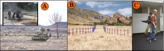
In the images above, item A shows a virtual enemy tank embedded in a real world scene. We provided similar AR targets in our Virtual Target Gunnery System which supports weapons, such as the Mark 38 machine gun (see item A inset) with an ability to engage dynamic targets with either live fire or dry fire.
Item B shows the use of AR to present command and control graphics to the user, embedded into their real-world, real-time view. This mine-filed breach is displayed to a military platform driver through a system called the Glass Turret Visualization System that was developed by our firm from 2000-2003.
Item C presents a view of a virtual opposing force that is being dynamically occluded by a person walking in front of the virtual entity. This a view from the DARTS system described in this paper.
Areas Requiring Additional Effort
At the end of this effort, we assessed the state of the DARTS demonstrator system and identified several items that should be addressed in future DARTS research:
Integration of OLED-based Binocular HMD: Now that we have determined that there are some affordable HMD systems on the market that can be used to support dismounted AR, we would like to integrate one of these into our DARTS system.
Integrated Helmet Sensor Suite: The DARTS effort is a relatively small research and development effort. Because of this, we are making every effort to expend contract resources only on those efforts that enhance the state-of-the-art in AR. However, the current state of the helmet is not attractive and may need to be refined before it is used in a large public demonstration.
Areas Requiring Additional Research
In our base effort, we have identified three areas which will require additional improvement in order to achieve our goal for a believable and wearable AR system. These areas are:
Improved Real-time Occultation — In the Base effort we were able to improve our occultation by replacing our scanning camera system with a camera system that captures an entire image in a single instant. This allows us to eliminate what we will call the “train effect” in our occultation data. When the scanning cameras collect an image while the user is moving his head from side to side, the side to side motion causes pixels at the bottom of the picture to be captured later than those from the top of the picture. This delayed capture of pixels can cause objects to be distorted, so that the lower part of the object appears to trail out to the side (the distortion looks similar to the train on a wedding gown or other highly formal dress—hence our name for the effect). The second effect to correct for is the halo effect around objects. This is caused because CPU limitations do not allow us to sample every pixel in a pair of images. We have developed an algorithm to greatly reduce (hopefully eliminate) this effect which we call the “deformable windows approach”. This is briefly described in the next section.
Distributed Parallel Processing — Integrate research on parallel processing on Graphical Processing Units (GPUs) to optimize CPU usage and minimize hardware requirement.
Improved Position Tracking/Pose Recovery — Reduce or eliminate reliance on wireless positioning. Integrate improved point tracking algorithm developed in this phase into demonstration system.
Deformable Windows for Improved Occultation
With stereovision, we find the distance to a point by finding that point in two side-by-side images, and measuring the shift of the point from one image to the next. In order to find which pixel in the right image is the match for a pixel in the left image, we take a window of pixels around the point in the left image, and compare the pixel values in that window to the windows around a set of pixels from the right image. We choose the pixel in the right image whose window matches best with the window around the pixel in the left image. For this technique to work well, the windows around each pixel need to have good texture, and they need to cover an area that has the same depth throughout the window. When a window straddles an area of an image with two different depths, it tends to produce a vague result, which makes it hard for the stereovision program to determine the depth correctly. Because of this problem, most stereovision systems do a poor job of correctly locating the edges between a nearby object and its background.
One approach that has been tried recently by stereovision researchers is to use deformable match windows. It is customary to use match windows that are centered on the pixels being compared, but it just as valid theoretically to use windows that are not centered on their pixels. The images below demonstrate this concept. We start with a pair of images from the UCF-IST parking lot. Notice the white truck in the foreground. Its position is shifted between the left image and the right one. We can find the distance to the truck by matching points between the images. However, if we look at the selected windows at the rear of the truck, we can see that half of each window is over the truck, and the other half is over a more distant background area. The selected points at the center of each window are actually part of the background, and not part of the truck, so a stereovision system should determine that this point is farther away than the truck. However, a stereovision system using compare windows like this would probably calculate that this point is at the same distance as the truck.
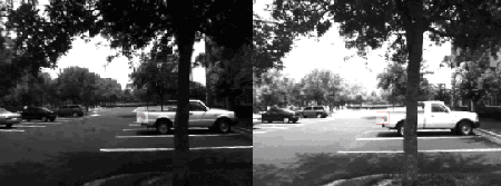

If we use a typical stereo vision system on this pair of images, it would probably find the correct distance to the truck, but it would create a false distance halo around the truck as well. In this false distance halo, the more distant background pixels would be falsely reported as having the same distance as the less distant truck. This halo will have half to two-thirds the width of our compare window. We can try to use a smaller compare window to reduce this effect, but this causes more false matches because a small window can not capture as much image texture. A better solution is to use windows that do not straddle a distance boundary. In the images below we are comparing windows around the same point as before, but now the windows are shifted to the side, so that they mostly cover the background. Windows like this are more likely to determine that this point is part of the background and not part of the truck.
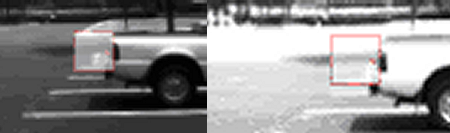
In order to apply this approach in a stereovision system, we need to have a way to determine when a point is near an edge where distances change suddenly, and we need to be able to determine which way to shift the window so that it covers an area that is mostly on the background, or mostly on the closer object. We will start by comparing all of the pixels in the image using the standard approach, which compare windows centered on the pixels being matched. Then the program will look through the image for areas where the distance changes suddenly. At this point we will assume that we have not found the true edge where the distance changes and we will approach that edge from either side with shifted windows. We should be able to find a correct distance for many pixels that previously had false results. We will not be able to eliminate false matches along edges with this approach, but we can hopefully make a significant improvement.
Computer vision researchers have tried a number of techniques like this over the last 20 years to try to improve the quality of the results from stereovision. In most cases, they have been able to show some benefit, but they have frequently found the computing cost very high. As computers get faster and faster, we are reaching a point where it is possible to use several refinement steps to correct errors that arise with various kinds of images. This approach using deformable windows is one of several that we plan to evaluate. We hope to combine several of the most promising approaches to achieve a high level of overall accuracy and robustness.
DARTS Program Lessons Learned
Here we present the lessons that we learned over the course of this research effort.
-
We found that our sensor set, which includes the wireless position sensor, the inertial position sensor, and the stereo vision cameras, is able to provide us with the raw data that we need to achieve effective AR. Our software will be able to perform successfully without the need for any other sensor inputs.
-
We found that adding the ability to move around with the DARTS system and the ability to connect to other simulators using a DIS interface added significant complexity, which required an extensive integration test effort.
-
We found that we needed to be aware of unique coordinate system definitions. Our core DARTS system has an internal coordinate system, so that the position of virtual objects can be related to the position of the DARTS user. As we added various features and capabilities to the system, we encountered a variety of unique coordinate system definitions, which required coordinate conversions to achieve compatibility. These coordinate conversions are very difficult to visualize based on mathematical formulas alone, so that we could not be certain that our conversion was correct until we could test the visual output of the DARTS system to confirm that virtual objects displayed and moved as expected. One of the key tasks we had to accomplish to integrate the DARTS system with the ICV for our demonstration at STTC was to visually test the appearance of our DARTS entity on the screens of the ICV, and adjust conversion parameters until the virtual entity moved the same on the screen as the DARTS user moved in reality.
-
We found that the believability of a virtual object in AR is strongly affected by the quality of the 3D models used. It is important to use highly detailed models for virtual objects, and to add realistic visual cues like lighting and shadows to make the virtual object look more like it exists in some position in real space. The models that are used for typical simulations tend to have a low level of detail. These models are good enough in a simulation setting, because they usually appear far away on the screen, and because all of the simulation has an artificial appearance. However, when virtual objects are viewed against a real scene, they need greater realism to achieve good believability.
-
Power requirements must include hardware for demonstration support up front. In our development process, we initially needed power for our laptop, video cameras, and inertial position sensor. As we added additional components to enable us to transmit an output image for demonstration purposes, we found ourselves having to supply multiple voltages, using multiple battery packs. In order to accommodate all of the components and wiring, we went through several configurations as we changed various features. We determined that we need to plan for all of our system requirements from the start when making further changes to the system.
-
Hardware must be ruggedized to support development. We had a number of problems during development of the system due to touchy, delicate components that worked well on a test bench but worked poorly when using the system in a wearable, mobile configuration. We found that it is necessary to work with component suppliers to find rugged components, and then make sure that our mounting and wiring arrangements allowed maximum stability during mobile operation.
-
Early end to end operation is a necessity to push development. Our development process required us to achieve several discrete capabilities, such as a DIS interface, or integration of our wireless positioning system. We were not able to do complete end-to-end mobile testing until all of these features or subsystems were implemented. We found that even though our subsystems all worked separately, and even though the system worked well on the test bench, there were unforeseen difficulties with operating the system in a man-worn, mobile configuration. We determined that it is important to get an end-to-end system working as quickly as possible, to allow for unexpected problems to be discovered and dealt with.
-
We found that our wireless positioning system is able to provide position data with a relatively small error rate, but when we tested the complete DARTS system outdoors in a mobile configuration, there were frequent interruptions of the wireless signal used to determine position. We concluded that signal interruptions like this are likely to be common in a typical DARTS training scenario, so we will work to minimize our reliance on external positioning data. At most, we hope to use this data as an occasional reference point to ensure that our continuous estimate of position remains accurate.
-
Accommodating free movement is achievable but difficult. We found that operating the system on the test bench was much easier that operating the system in a man worn, mobile configuration. Components and wiring connections that worked well on the test bench tended to cause our computer to freeze when we tried to wear the system. We had to replace, remount, or rewire components to improve their stability. We also found that sensor data is more ambiguous when moving around, which required us to carefully tune our software to provide acceptable results. One of the major goals of our follow up effort will be to enable the system to compensate for tiny changes in the configuration of the sensors without reductions in performance.
AR’s Potential Benefits for the Warfighter
We have identified the following uses of AR in meeting military training requirements:
-
TARGETS — The needs of the war fighter demand the creation of a new generation of range targets. This new generation of targets must represent a large spectrum of friendly, enemy and neutral platforms/individuals in order to support preparations necessary to succeed in today’s complex operational environment. Targets must be able to react to trainee actions and present credible complex behaviors. In addition to all of this, future targets must be observable while operating in day, night and obscured conditions as well as be observed by Night Vision Goggles or other sensor systems. Clearly AR is a reasonable candidate to meet these future requirements as AR targets can be used to support live fire, FTXs and dry fire exercises without the need for extensive range infrastructure. AR targets can be embedded into the Warfighter’s systems and equipment.
-
COMMAND & CONTROL and EXERCISE CONTROL MEASURES — The Combat Training Centers (CTCs) demand that units execute complex operations while under observation by CTC staff. Frequently, CTC staff must quickly insert themselves into the training environment to ensure that units are adequately and safely trained. These same CTC staff members may be dispatched at a moment’s notice to observe unit operations. The use of AR to help control the conduct of complex training maneuvers and ensure training safety is an application of AR that should be improved.
-
SEAMLESS LIVE/VIRTUAL/CONSTRUCTIVE INTEROPERATION — Today, most large scale exercises are no longer performed exclusively on live ranges. Large exercises usually have live/virtual and constructive training components that are executed simultaneously. A noticeable shortcoming of these combined exercises is the inability of the training force operating in the Live component of the exercise to see his virtual or constructive counterparts. This lack of seamless operation is handled today with the insertion of Observer/Controllers or elaborate workarounds that minimize this shortcoming. Providing forces operating in the Live domain with a view of constructive and virtual entities would eliminate the need for these unrealistic workarounds. Such an AR solution would also allow for exercise planners to inject larger opposing force or friendly force components into exercises to present more challenging training.
-
SYSTEM RECOGNITION — Today’s operations demand that warfighters are able to quickly identify friendly, enemy and neutral forces at a moments notice. AR could be used at training sites and while in the operational theater to hone system recognition skills to decrease decision cycle times and reduce the potential of fratricide.
-
AFTER ACTION REVIEW ANIMATION — After a unit has completed a maneuver, AR could be used to allow unit members to walk through their maneuver and examine their decisions and actions at critical points. These scene animations could be used with later units to show how previous units executed the maneuvers. This could be a particular value in small unit operations associated with urban combat.
-
PRESENTATION OF SAFETY INFORMATION — Whenever live fire exercises are conducted, there always exists the possibility that someone could be injured or killed. AR could be used to further reinforce left and right range limits, range boundaries, hot ranges and ranges that have been temporarily closed until a weapon malfunction or other problem has been resolved.
-
MISSION REHEARSAL — AR could be used to virtually construct key elements of terrain for upcoming operations. This would allow units to conduct more realistic mission rehearsals to improve their chance for mission success. AR could also be used to present complex “what if” situations that could be used to refine the final plan or help develop contingencies should problems arise.
-
PRESENTATION OF OPERATIONAL COMMAND & CONTROL — GRAPHICS— In the past, we have used AR to present operational graphics on actual terrain in real time to enhance situational awareness. The use of AR in this context ensures that operational graphics can be met in all light and weather conditions. It also decreases the time necessary to make decisions as it eliminates the time currently used to associate the operational graphics presented on maps by integrating them into the soldier’s real-world, real-time view.
-
NAVIGATION FOR OPERATIONS AND TRAINING — Like the description in the previous bullet, AR can be used to present real-time navigation information to platform drivers and dismounted soldiers.
-
VIRTUAL OBSTACLE MARKING — Today’s operational theaters are full of obstacles and hazards to be avoided. Oftentimes, markers showing paths through or around these obstacles are lost. Weather conditions can frequently make these markers impossible to view. The use of AR to mark obstacle passages could help save soldiers by safely guiding them around or through barriers and obstacles.
-
FORWARD OBSERVER TRAINING — One of the first applications for military training that we identified was the use of AR for Forward Observer training. In this application, one could inject targets and virtual forces into the view of the forward observer (through a vision block, weapon sight, binocular or other device) and allow the Forward Observer to determine if the entity is a target, and if so, how to best prosecute it. Such a system would be of great use to artillery units who rarely see the fruit of their labors. The View of the Forward Observer as a target is prosecuted could be recorded, or even transmitted back to the artillery for later discussion at an After Action Review (AAR).
Conclusion
Each day that goes by, LVC integration moves forward without a key component for full integration across the training domains—a capability for the live player to see and interact within the LVC integrated battlespace. As technology continues to improve and advance, Army leadership must recognize the potential for use of Augmented Reality tools and techniques and the capability of this technology to supplement existing and future training systems.
A soon-to-be-published Augmented Technology Roadmap will provide training leadership and technology management with options for implementing augmented and mixed reality solutions for current and future training and operational requirements. Although approaches for technical solutions is wide and varied, there are some possible “out of the box” solutions that can be leveraged very quickly. For example, with some further development the DARTS system could be prepared for a demonstration that is synched with an upcoming or planned training experiment. Used possibly in the role of a forward observer, the DARTS system would provide training leadership with exposure to Augmented Reality in a relevant environment. Additionally, soldiers would have an opportunity for hands-on experience, leading to valuable comments and other input for future development.
The Way Ahead
Advise training and testing communities and leadership about the capabilities and potential of Augmented Reality.
Seek assistance and endorsements from stakeholders.
Include AR research in future Army Technology Objectives (ATO) AND Small Business Innovation Research (SBIR) topics; and continue development under multiple ATOs.
Demonstrate useful technology to leadership and requirements generators.
Plan for and transition Augmented Reality capabilities into existing and planned acquisition programs.
About the Authors
Frank Dean is currently a principal investigator and S&T manager with the Simulation & Training Technology Center (STTC), RDECOM, Orlando, Florida. Mr. Dean manages R&D projects related to the enhancement of experiential learning and training of the Warfighter, by using augmented and mixed reality technologies. Mr. Dean has over twenty years of experience with various military weapons systems acquisition and technology programs. Prior to his assignment to RDECOM, Mr. Dean managed engineering projects for the PEO Simulation, Training & Instrumentation (PEO STRI), including operations and maintenance of the National Training Center Instrumentation System (NTCIS), Ft. Irwin, California. Mr. Dean holds a bachelor of science in electrical engineering (BSEE) from the University of Miami in 1982 and a master of engineering management (MEM) from George Washington University in 1994.
Sheila Jaszlics is the President of Pathfinder Systems, Inc. and has been pursuing AR for military training and operations since 1991. She is co-author for a US Patent describing real-time injection of virtual entities in real-time scenes (US Patent 6,166,744).
Scot Sanders is a graduate of the University of Northern Colorado. He has been with Pathfinder Systems, Inc. for several years and has been a key developer of the baseline system software and hardware interfaces that are used in all of Pathfinder’s AR systems. In addition, Scot is the creator of the high fidelity azimuth and elevation sensor suite used on all of Pathfinder’s AR systems that support live fire for crew-served weapons. He is also a developer of the Kalman filter software that is used to extract and smooth the data we receive from the hybrid sensor suites that we use in all of our systems.
Rick Stilson is a graduate of the Colorado School of Mines and is the author of much of the pose recovery software that was developed under this effort. He was also responsible for much of the DARTS system software and tracking system hardware. As an employee of Pathfinder Systems, he provides expertise in all technical areas associated with stereo vision algorithms. He is the engineer in charge of developing the “deformable windows” approach to edge finding which we will implement to improve the quality of our real-time occultation data.